The DT5550W is a ASIC reliable prototyping board designed to readout Analog and Digital ASIC. This platform is designed for imaging purpose: Calorimetry, Silicon Tracker, Medical Imaging.
The platform offer up to 220 digital high speed I/O and 8, 80 MSPS 14 bit ADC channels. Almost all modern front-end ASIC can be validated with this system It is possible to read-out:
- Pre-amplifier/shaper only ASIC with dedicated Analog output for each channels
- Multiplexed channels Analog Output ASIC
- Digital only ASIC, for example ASIC with only comparator insiede designed for applications requiring only timing information
- ASIC with integrated ADC and/or TDC
- 50 ps resolution TDC on Petiroc ASIC
SCICompiler implements all Virtual Blocks to:
- Implements trapezoidal filter or charge integration to measure the energy of the pulses
- 0.5ns TDC in order to timestamp events and implement TOT
- Analog De-Multiplexer to readout data from multiplexed ASIC
- WeeROC ASIC Decoders blocks
- The DT5550W devices could interface to the ASICs slow control using SPI, I2C or Parallel interface.
DT5550W ASIC READOUT SYSTEM
The DT5550W system is based on a programmable FPGA that can be configured through a graphical developing platform. The platform can host different daughter cards to evaluate WeeRoc ASIC. The DT5550W can be used in laboratory to implement a full working experimental setup minimizing the development time and cost.
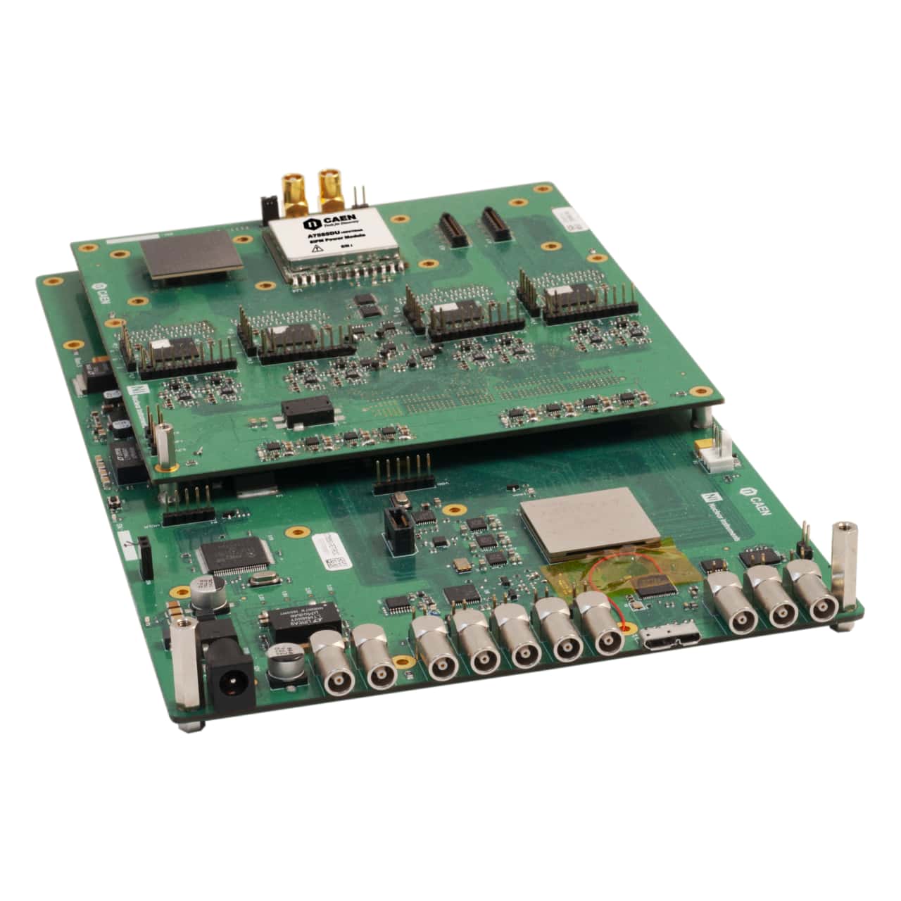
A5550P - FOUR PETIROC READOUT SYSTEM FOR SIPM MATRIX
For example, the PetiRoc development board A5550P hosts up to 4 Petiroc chips offering to the user the possibility to readout 128 SiPM detectors. The SiPM connectors fully matched with Hamamatsu S13361-3050NE-08 MPPC 64 channels Matrix. On the board, can be connected up to 2 matrices with the possibility to use an extension cable to arrange the two detectors in several geometry. The architecture of the digitizer DT5550W is designed to adapt, in a simple and intuitive way, the hardware acquisition architecture to the user configuration: more then 200 digital signals interconnect the mezzanine ASIC boards with the DT5550W in order to have the possibility to readout and monitor all signal from the ASICs with the FPGA. The DT5550W has an onboard 8 channels 80MSPS/14-bit simultaneous sampling ADC to monitor analog outputs from the chip. The A5550P board hosts up to 4 Petiroc chips offering to the user the possibility to readout 128 SiPM detectors. The SiPM connectors fully matched with Hamamatsu S13361-3050NE-08 MPPC 64 channels Matrix. On the board, can be connected up to 2 matrices with the possibility to use an extension cable to arrange the two detectors in several geometry. The board is fit with HV module to power both SiPM matrices (regulable voltage between 20 and 85V). The board routes all Petiroc pins to a 400 pin mezzanine connector. The board distribute the clock to all petiroc minimizing the jitter. It also generates all ASIC power supply using ultra low noise linear regulator
WEEROC PETIROC 2A ASIC
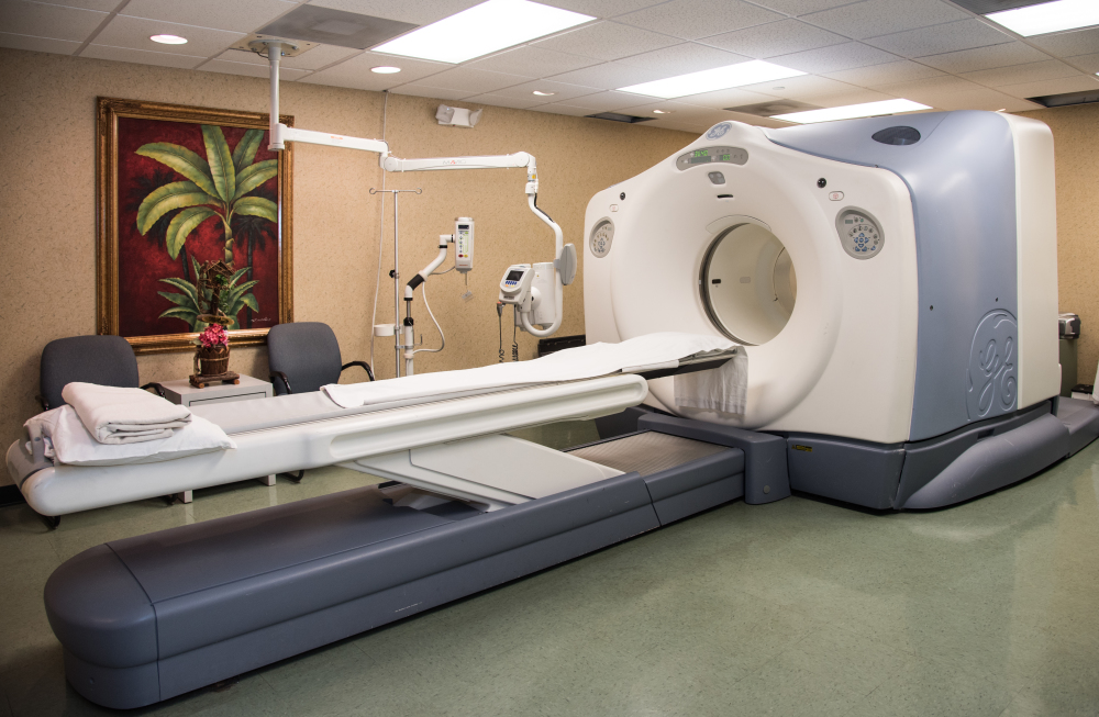
Petiroc2 is a 32-channel front-end ASIC designed to readout silicon photomultipliers (SiPM) with both polarities for particle time-of-flight measurement applications. Petiroc2 combines a very fast and low-jitter trigger with accurate charge and time measurements. Energy and time are digitized internally with a 10-bit ADC and 40ps-bin TDC. The concept of the ASIC is to combine two measurement lines that won’t interfere one with each other to measure both first incident photon timing measurement and whole crystal light charge integration. An adjustment of the SiPM high voltage is possible using a channel-by-channel input DAC. It allows a fine SiPM gain and dark noise adjustment at the system level to correct for the non-uniformity of SiPMs. The power consumption is 6 mW/channel, excluding buffers used to output the analogue signals. The main application of Petiroc 2 is PET time-of-flight prototyping but it can also be used for any application that requires both accurate time resolution and precise energy measurement.
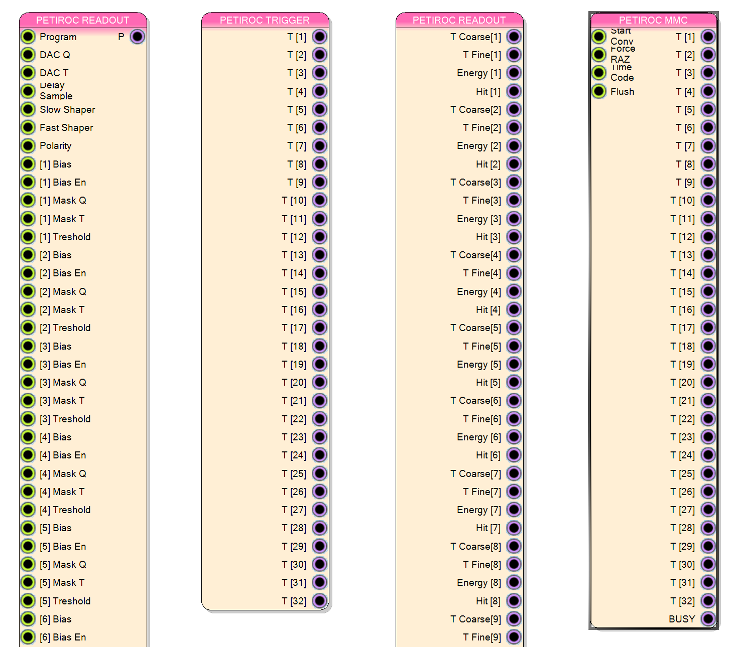
SCI-COMPILER PETIROC SUPPORT
At the moment SCICompiler supports Petiroc 2 chip only. The following virtual blocks are available in order to readout the PetiROC Chip Configuration Block: exports all configuration bits of the PetiRoc Chip
- Trigger: exposes all trigger output bit of the PetiROC chip
- Readout: deserialize PetiROC digital data output
- PetiROC memory mapped device: export the minimum number of I/O interface making the configuration and the readout of the PetiROC chip available only from PC
- The PetiROC memory mapped device minimize the development time allowing to connect external from the PetiROC chip the trigger logic only
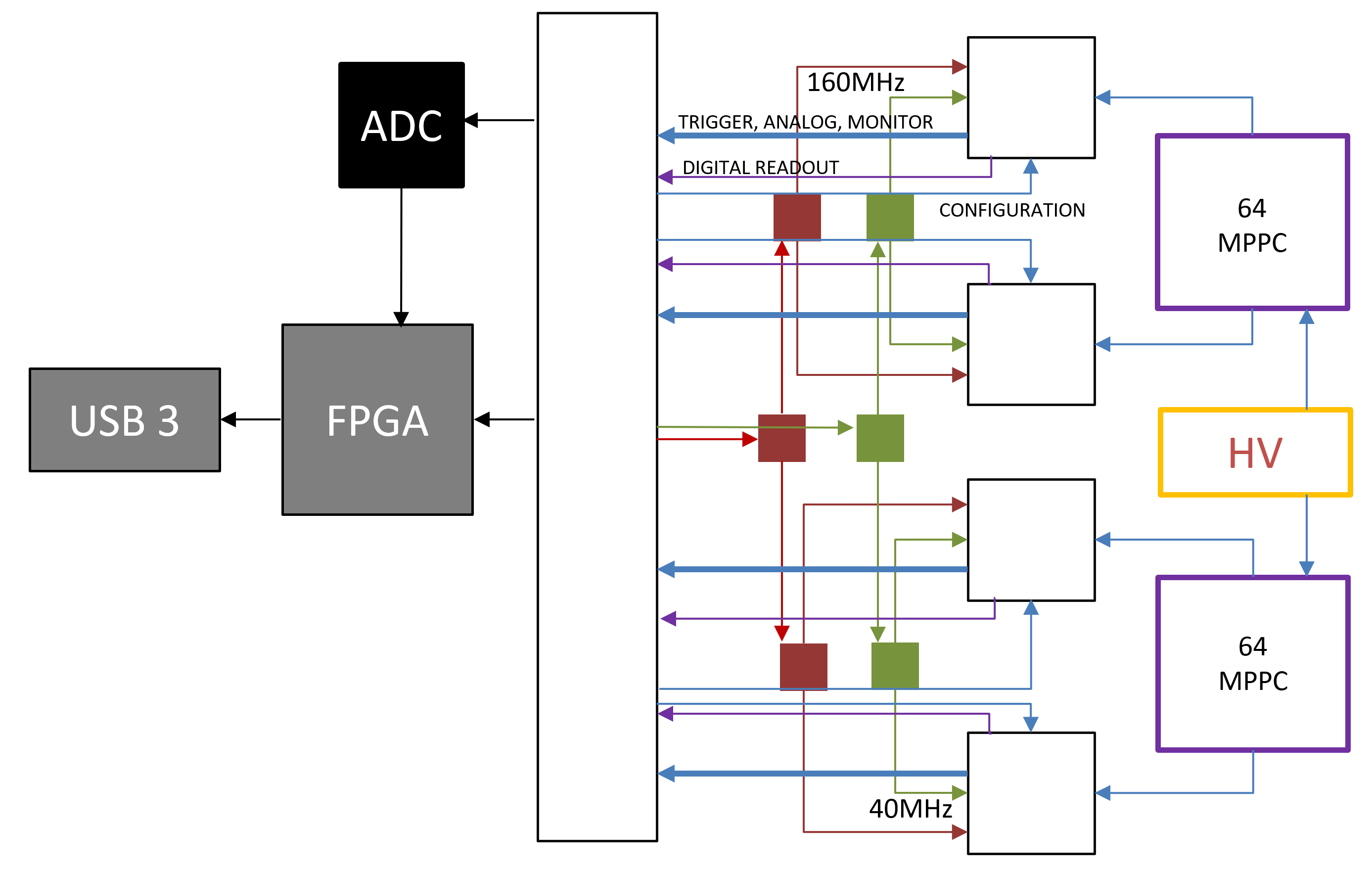
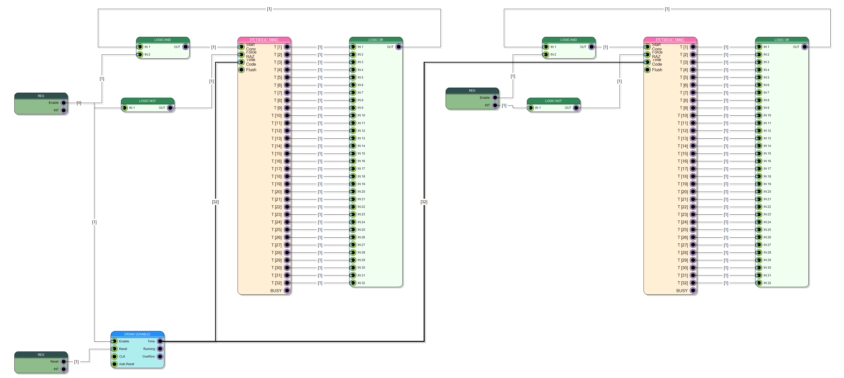
FIRMWARE OVERVIEW
The firmware implemented in this design readout data from two PetiROC. The two PetiROCs work indipendently each other reading each one half of the 64 pixel of the Matrix The syncronization between halves frame is made using the common timecode information generated by timecode block. Int the design, there are only two register (Enable and Reset) because all configuration register (more the 590) are implemented as dynamic registers of memory mapped Petiroc Readout Block The Petiroc Readout block hides inside the frame transfer logic and USB 3 controller interface.
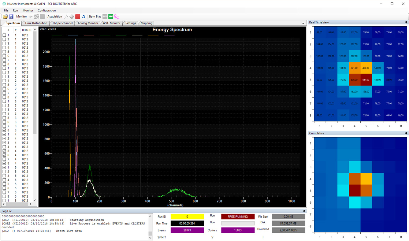
READOUT SOFTWARE
This application note is one of the complete solution distributed with the SCICompiler license. Ine SCICompiler package the full project and compiled version of the design is availabe. The Windows software is available for free and distributed in open source format. The software is written in VB.NET 2015 and it is very easy to costumize. The software is able to configure and readout two PetiROC ASICs. The intuitive GUI allows the user to:
- Configure the two PetiROC chip
- Dump on file all data in output of PetiROC ASIC in binary format or decoded in easy-to-read JSON format
- Execute realtime plot of:
- Image View both in single frame shot and cumulative image
- Energy Spectrum for each channels
- Time distribution in respect of one channels (assumed as T0)