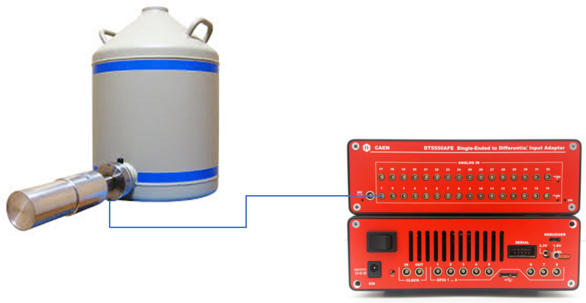
The DT5550-AFE board is a plugin module for the DT5550 designed to interface single ended output pre-amplifier with the analog differential input of the DT5550. The board has 32 indipendent single ended input and can be direct connected to the DT5550 analog input. The input impedance of each channel of the DT55550-AFE can be set as 50R or 1K The input dynamic range is +-2V with the possibility to regulate the offset to fit as best the ADC input DC range. This application note shows how to develop a firmware to acquire the waveform, impements a trapezoidal shaper and calculate the energy spectrum in realtime
MCA FIRMWARE STRUCTURE
A MultiChannel Analyzer is an hardware/firmware device that, with some analog/digital circuit calculate in the most possible accurate way the energy of each event in output of detector in order to generate a spectrum (histogram of energy). The are several way to implement a circuit with this function. The DT5550 platform offers the possibility to desig all the processing chain in a digital enviromental with the incredible advantage to have the possibility to develop it using the SCICompiler proccessing blocks. In a classic structure of a MCA is possible to identify two path:
- Fast path: trigger path, used to identify each events. The most important feature of this path is the low dead time and the capability to separate two events, even if the two signal are piled-up. This is necessary in order to recognize if the energy measured for an event is really related to a single event or it is the sum of different events.
- Slow path: energy path, used to calculate the energy of an event. This path must maximize the signal to noise ratio in order to obtain the best possible extimation of the pulse energy. It use the information of the trigger to accurate calculate the energy sampling time (ie: the 80% of the flat top of the trapezoidal filter) and also to discard piled-up events
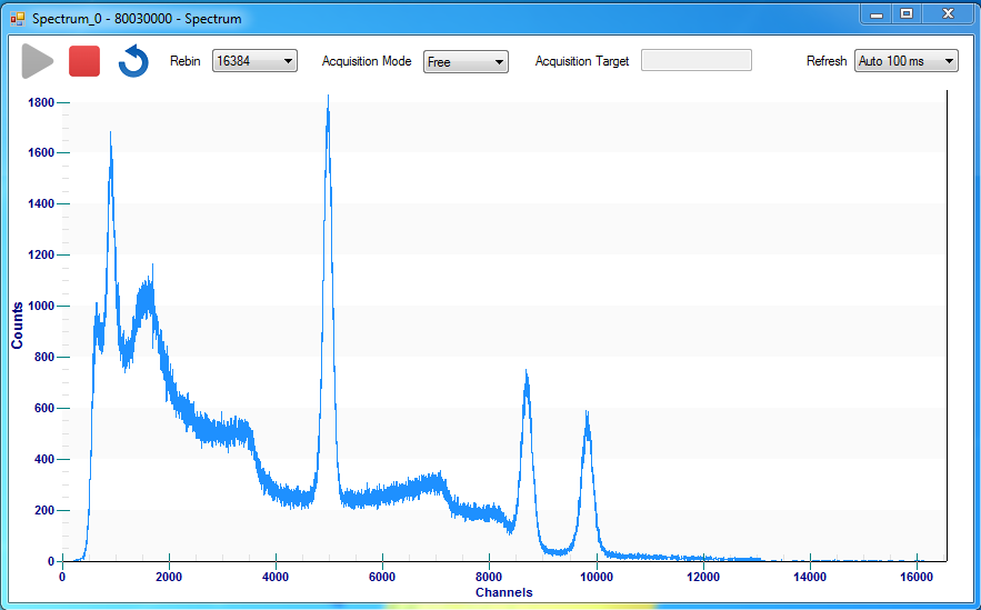
- Histogram: it implements the spectrum calculation blocks. On the DT5550 the spectrum can be calculated both inside the instruments or offline on the computer. In this example we will compute the spectrum offline on the computer. This is the great advantage to save FPGA ram (limited to 1 Mbyte) and to have the possibility to do not loose the timing information and have the possibility to reconstruct not only the spectrum but also an image of each events grouping togheter the information between different channels having a compatible timecode information. The SCICompiler offers also a real-time spectrum block that calculate onboard on the FPGA the spectrum.
TRIGGER LOGIC
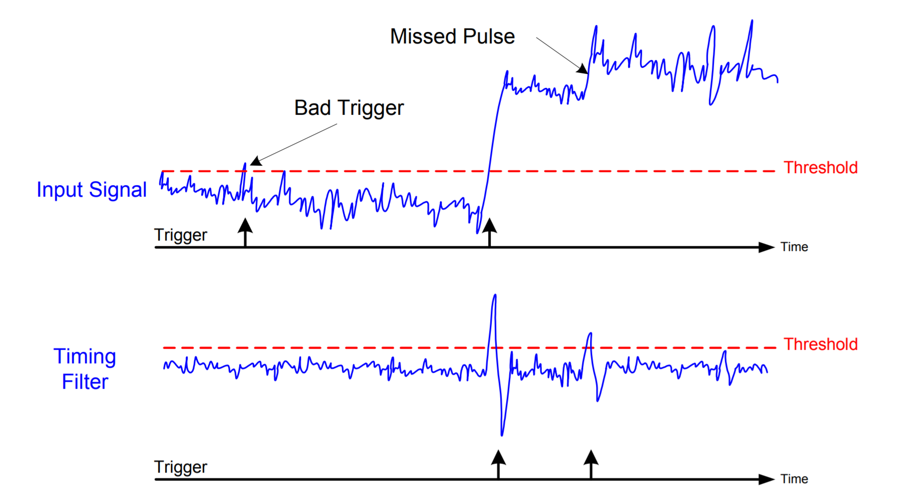
Usually, the digitizers and the oscilloscopes feature a self-trigger based on a programmable voltage threshold; the trigger is generated as soon as the input signal crosses that threshold (leading edge). Unfortunately, this technique is not suitable for most physics application because of the baseline fluctuation, pulse pile-up, noise, etc… However, the ability in finding all the good pulses and discriminating them from the noise is very important. In fact, missing pulses or false triggers can cause loss of important events, bad pile-up rejection, errors in the statistics and other unwanted effects. The digital filters are able to reject the noise, cancel the baseline and to do shape and timing analysis for this purpose. SCICompiler offer both simple leading edge and differential trigger with noise filter The derivative trigger calculate the drivate of the input signal as y[n] = x[n] – x[n-N] where N is a coefficient that scorrelate the noise between samples calculating the derivate not between adjacent samples but between farer ones. Moreover SCICompiler offers to the user the possibility to reduce the noise impact by the meaning of:
- Noise filter: a 4 sample fixed movig average filter, ideal for noise rejection on trigger
- Moving average: a programmable moving averabe box
- IIR filter: First order Input Infinite Response filter, multiple blocks can be cascaded in order to obtain an higher order filter
- FIR Filter (coming soon): Programmble arbitrary complexity FIR filter
TRAPEZOIDAL SHAPER
The optimum weighting function for charge collection is a constant for the duration of the charge collection process (a few tenths of a microsecond typically). The optimum weighting function for the noise encountered in detector-FET amplifier systems, and under the constraint of finite measurement time per event, is a finite width cusp), if zero collection time is assumed. The finite width cusp approaches a triangle if its width is less than two noise corner time constants. Thus, the optimum composite weighting function for these two entirely different causes of line broadening is a trapezoidal function. For this function the width of the constant portion is determined by the charge collection time, and the width of the two triangular portions is determined by the noise. [TRAPEZOIDAL FILTERING OF SIGNALS FROM LARGE GERMANIUM DETECTORS AT HIGH RATES, V. Radeka, NUCLEAR INSTRUMENTS AND METHODS 99 (1972) 525-539]
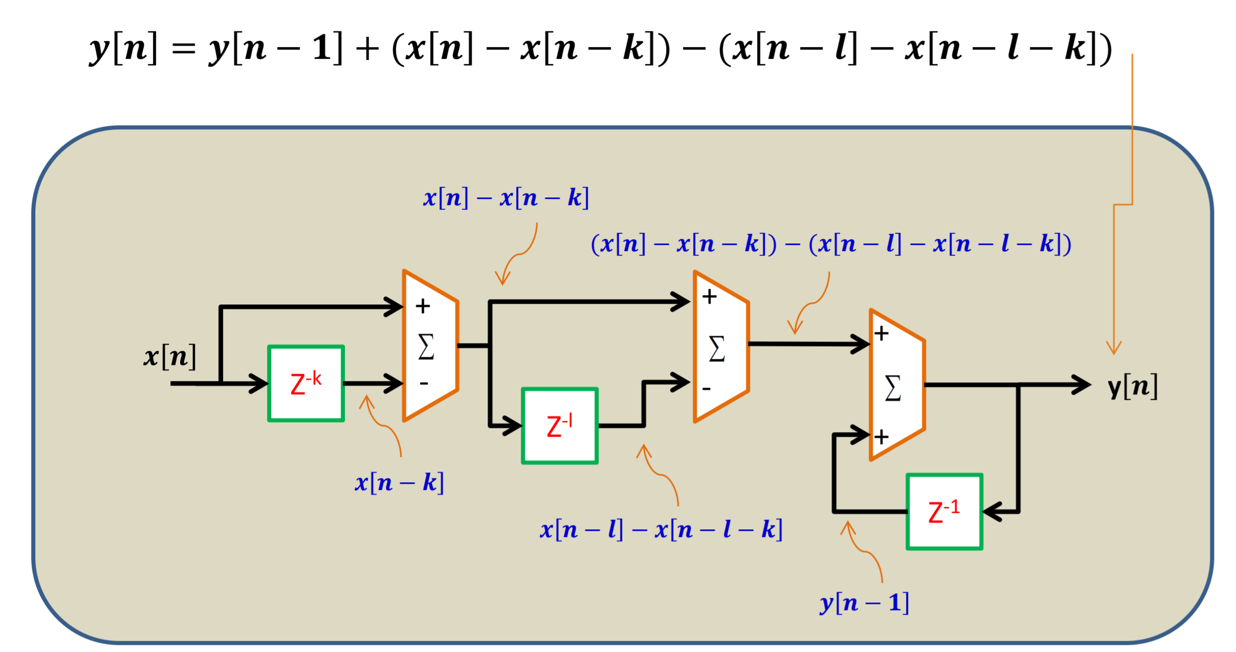
SCICompiler iplements a recursive trapezoidal filter. This is the best way to implement a realtime shaper architecture in a FPGA device. It use only shift registers (RAM), a multiplier and two a accumulator in order to implement the desidered shaping function.
FIRMWARE OVERVIEW
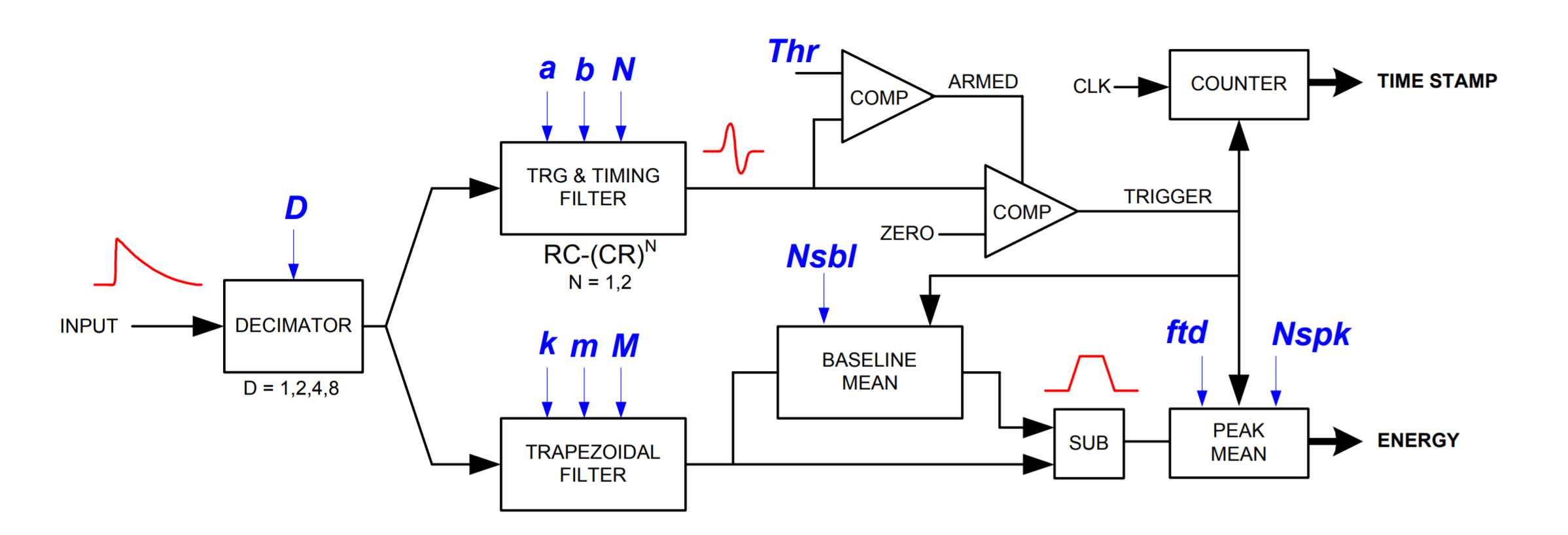
The firmware diagram is composed by 5 blocks
- 32 Processing Units that contains: trigger, baseline restorer, trapezoidal filter, energy sampling block
- Frame transfer module: merge data from all processing blocks and trasnfer energy and timecode information to the PC and implements the PC communication
- Oscilloscope: dumps waveform and transfer it to the control PC
- Memory mapped I2C transfer controller to configure HV generator
- Configuration register: configure filter parameters
OSCILLOSCPE
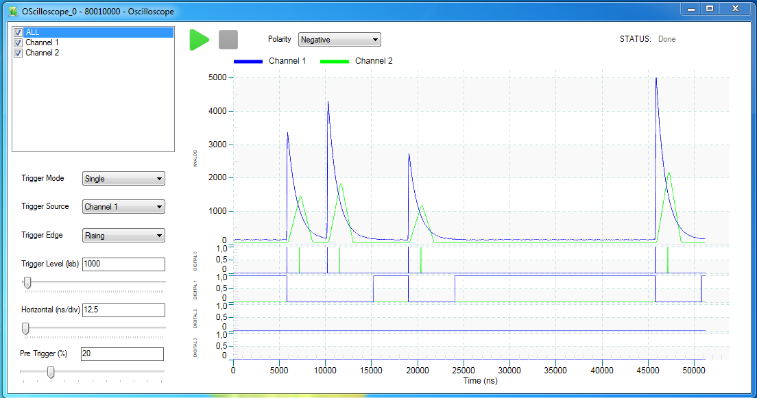
OSCILLOSCPE The oscilloscope dumps waveforms from multiple channels as analog signal. Each oscilloscope channel has one analog input and four digital inputs. On computer side oscilloscope data can be saved on file or ploted in real-time. SCICompiler includes C# / VB.NET GUI examples to control and plot data from oscilloscope As a real oscilloscope SCICompiler Oscilloscope Virtual Box has four different trigger mode:
- Free running
- Leading edge trigger on any of the input analog channels
- Digital trigger on any of the input digital channels
- External Trigger
- Trigger can be configured to operate on rising or falling edge
PROCESSING CORE
- Signal inversion to accept both positive and negative polarity signals
- Derivative trigger with programmable treshold
- Baseline restorer based on programmable length moving average
- Trapezoidal filter with integrated baseline subtraction and pileup restorer
- Energy sampler: delay the trigger signal in order to sample the trapezoidal filter output in the desidered point of the flat top
- Analog monitor multiplexer: select which between, input signal, trapezoidel shaper, baseline, energy analog signal connects to the oscilloscope channel input
SCI-DIGITIZER SOFTWARE
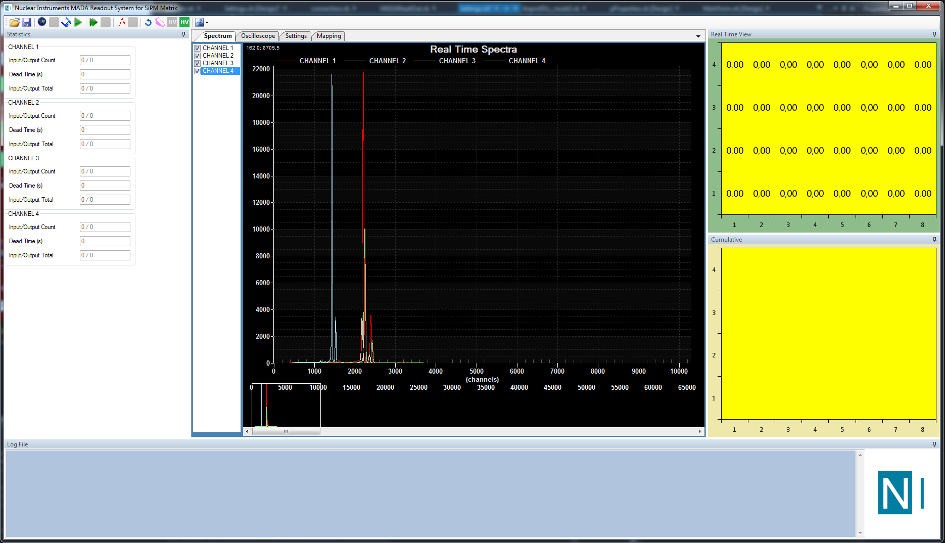
The SCI-5550 Readout Software is the free and open source Windows-based software developed to perform acquisitions with the DT5550. It works in conjunction with the DT5550 default firmware and it can be modified by the user according to the custom functions implemented in the firmware and for any other need.