High speed readout electronics for new generation Pulsed Muon Spectrometers

A.Abba (2), F. Caponio (2), D E Pooley(1) , F A Akeroyd(1) , P J Baker(1) , D. Kirk (1) , S P Cottrell(1) , R. Stewart (1) , A. Hillier(1) , C Macwaters(1) , D Nixon(1) , N J Rhodes(1) , E M Schooneveld(1) , D Templeman(1) , Z, Clark(1) , L. Pastori (2)

STFC, Rutherford Appleton Laboratory, Harwell Campus, Didcot, OX11 0QX, UK

Nuclear Instruments SRL, Lambrugo (CO)

Many muon events are detected, with only those above a pre-defined threshold (red line) being counted. The data pipeline processes this data into muon decay histograms. Muon decay histogram with and without severe dead time (in blue) distortion at early times in respect of the ideal lifetime curve (orange)

The proposed ‘Digital Data Pipeline’ (DDP) leverages digital signal processing (DSP) and modern computing power to maximize information extraction from muon decay histograms. It involves recording raw detector signals with high fidelity, processing them in situ, and storing them for real-time analysis by software tools. DDP is motivated by the needs of next-generation pulsed muon spectrometers like the proposed Super-MuSR at ISIS, which requires a count rate capability of approximately 1 G·event·hr-1.

This instrument is designed to count around 10,000 muons delivered to the sample a few tens of nano-seconds post-accelerator pulse, ensuring muon de- cay histograms are free from dead time distortion due to event pileup.

Recent advancements in muon spectrometers include the use of compact silicon photomultipliers (SiPMs), which offer excellent temporal resolution and magnetic field insensitivity.

Their size enables the creation of highly pixelated arrays to handle high rates at pulsed sources, though their long recovery time compared to tradi- tional photomultiplier tubes is a challenge. Addressing this, signal processing is considered essential to achieve high-rate capabilities with SiPMs.In this context, an ‘event’ refers to the volt- age signal generated in the detector when a muon decay product (positron or electron) passes through the scintillator, typically lasting a few tens of ns.

A ‘trace’ is the broader voltage signal measured around the muon pulse, currently spanning about 32 μs, which will extend as flux increases. Each accelerator pulse and associated trace, known as a ‘frame,’ contains several events.

The new DDP will process and stream data during the 19.68 ms idle time between muon pulses.

Any dead time distortion disproportionately affects the data at early times where rates are very high, which, in turn, negatively impacts on the modeling and scientific understanding of the results. Dead time distortion arises when the detector system is overwhelmed by the rate of incoming events, becoming paralyzed after each detection and failing to register further events until the system has ‘recovered’. A muon measurement is particularly challenging, as the signal of interest is a small modulation on top of the 2.2 μs mean lifetime of the muon. Consequently, the detector must be able to instantaneously and accurately count very high data rates immediately following implantation of the muon pulse, falling back to almost zero counts after a few muon lifetimes.

Focus on DAQ121:

  • 32 channels, 1 Gsps 12/14 bit readout system designed for muon instruments
  • Up to 120kpoints/ch memory depth @ 80 Hz om 4 Gbps link
  • 5 FPGA + 16 cores @ 1.5 GHz for real time signal processing
  • Easy integrable in ISIS (or others) facili- ty: IBEX for slow control and Kafka for readout
  • ZeroMQ + JSON side monitoring readout
  • Integrated controller for pre-amplifier and SiPM bias
  • 60 digital I/O (TTL+LVDS)
  • Fully differential 2vpp inputs
  • Open source firmware and software

SuperMUSR SiPM Detector

(a) SuperMUSR detector design populated with all staves front end. (b) picture of the first prototype of the stave detector designed for 8 tiles. (c) new stave design with 32 channels preamplifier (d) side view of the stave detector with, in section, the liquid cooling systems. (e) plastic scintillator with optical fiber inside to collect light.

A crucial element of the detector is the stave, which is the detector preamplifier system that enables the conversion of the positron from the muon dacey into an electrical signal measurable by the digitizer system. Each stave consists of 8 sections of scintillators, which in turn
are divided into 4 plastic scintillators where light is collected by optical fibers. The two sides of the fibers are read by two SiPMs each, and then analogically summed to collect light from both ends. The SiPM signal is converted into voltage through a resistor and then amplified. Downstream of the amplifier is an analog pole-zero to remove the SiPM’s slow constant, followed by another amplification stage and finally a differential driver for CAT6 cables. In addition to amplifying the signal, the stave is designed to regulate the bias of each SiPM by changing the voltage on the anode.

The stave is cooled using liquid. The SiPMs have a strong temperature dependence on gain. To stabilize the temperature set by the liquid cooling, the stave incorporates serpentine circuits in the PCB underneath the SiPMs, which are controlled by a microcontroller in order to stabilize the temperature of the SiPMs within 0.2°C.

Block diagram of the stave. The signal form the SiPM is amplified using a complex chain of pre-amplifier includ- ing pole-zero compensation. The temperature of the SiPM is stabilized using a PID regulator that drive a serpentine under the detector. Each SiPM bias voltage is regulated in order to match the gain in function of calibration and T.

ADC121 Digitizer

The DAQ121 is a new digitizer and real-time signal processor, developed in the collaboration between Nuclear Instruments and UKRI for the ISIS muon spectrometers. It employs four Xilinx Zynq UltraScale+ System on Chip (SoC) per module, integrating FPGAs, quad-core ARM processors, and DDR4 memory. This SoC manages parallel acquisition processes, interfaces with GHz ADCs (12 and 14 bits). It also calculates real-time noise profiles for SiPMs and processes signals with complex DSP algorithms during the 19.68 ms idle time between ISIS frames. The data is formatted using Google flatbuffers for

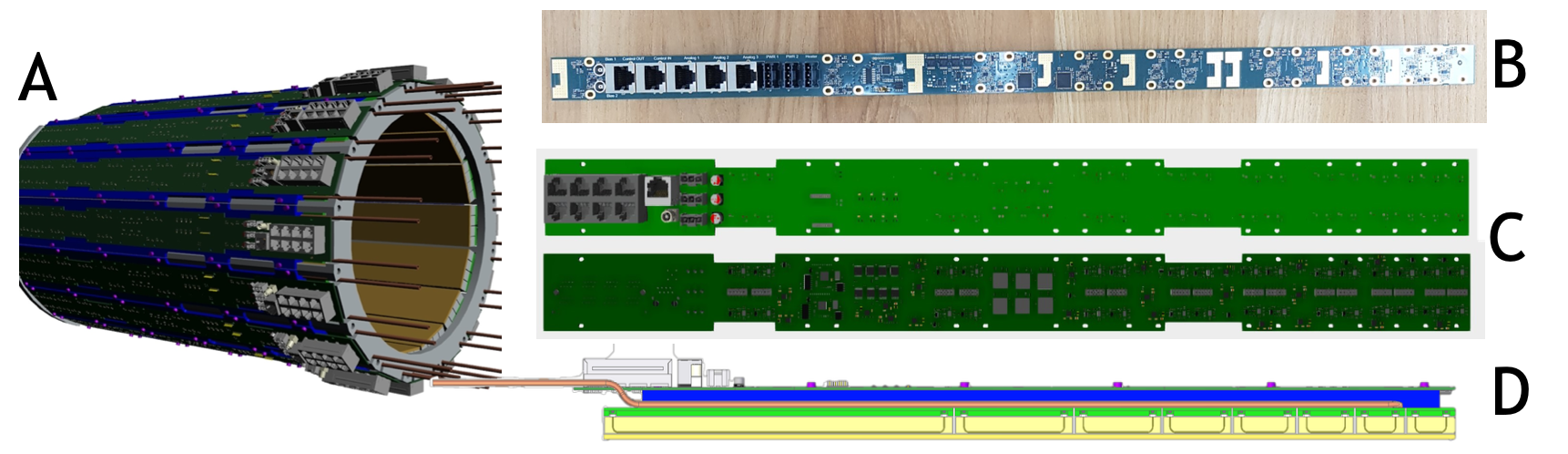
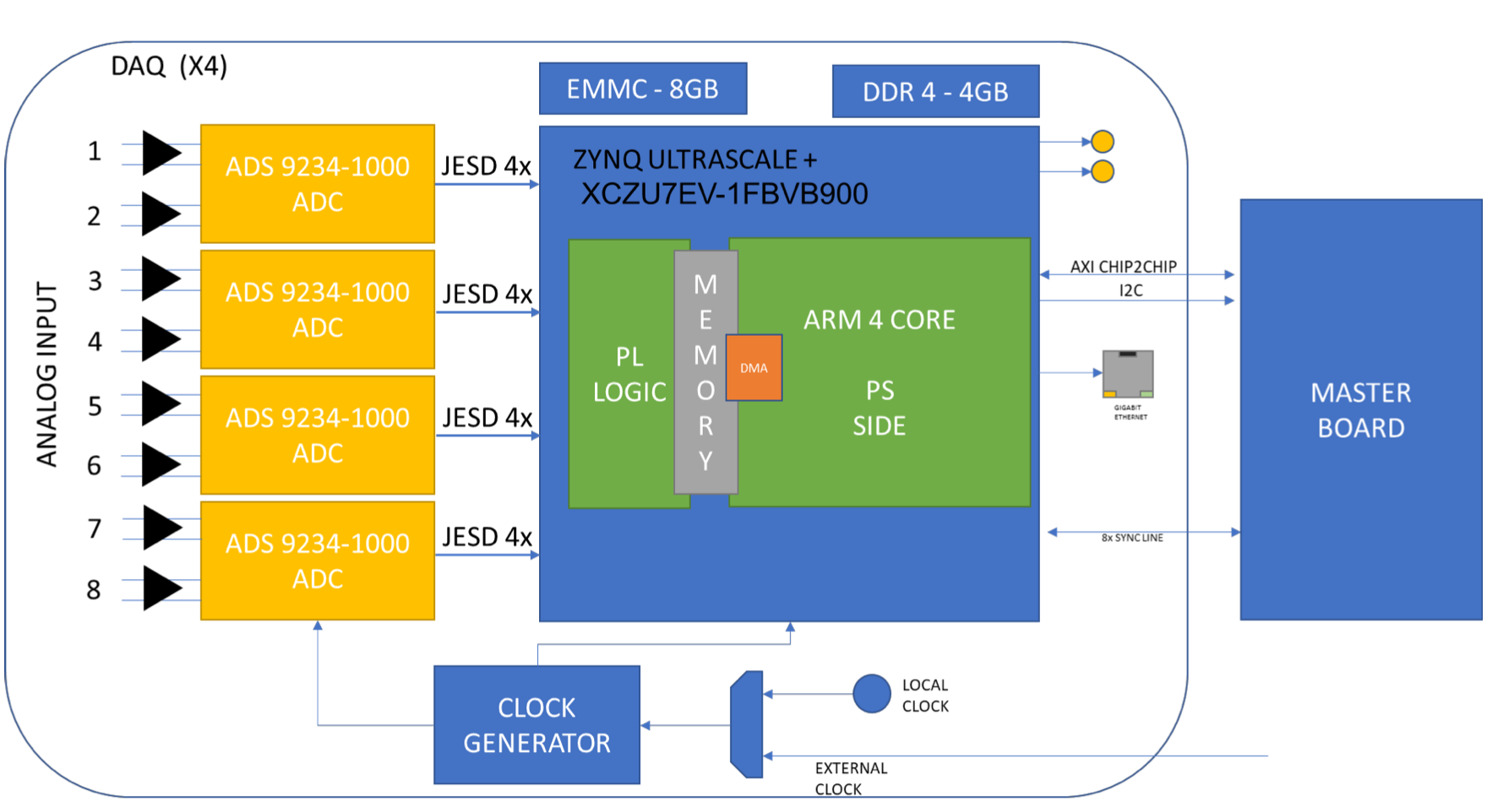
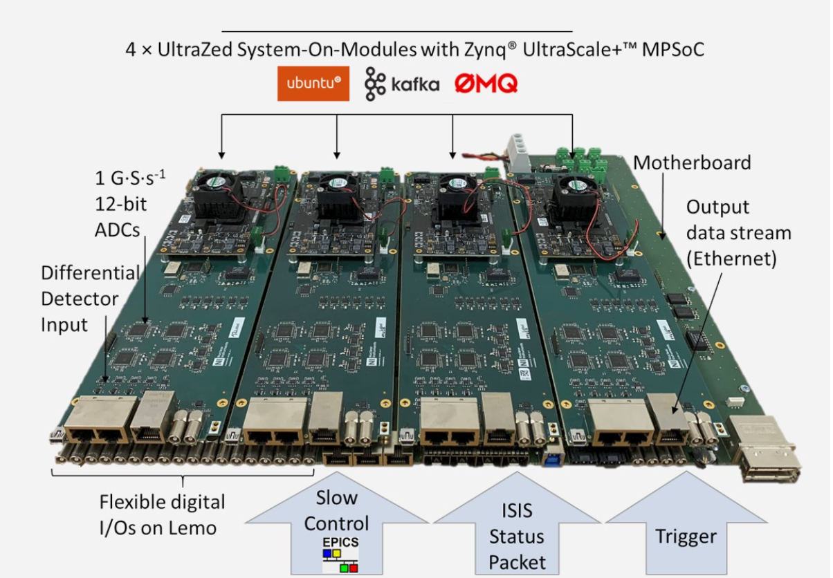
output via Apache Kafka or ZeroMQ. The system, running Ubuntu Linux, supports in situ software development for DSP , data streaming, and slow control operations like measurement management and diagnostic parameter acquisition (e.g., thermometry from SiPMs). Users can adjust acquisition parameters, which are controllable via the ISIS instrument. control computer using the IBEX interface, based on the EPICS toolkit and interfacing through ZeroMQ. The data demands of Super-MuSR at ISIS have led to the adoption of a novel data acquisition architecture, akin to the live data streaming approach used for the European Spallation Source. The instrument at hand is composed of four DAQs and a base. Each DAQ houses four ADCs, ei-

ther 12 or 14 bits each, with two channels, summing up to a total of eight ADC channels. These ADCs are connected via JESD to a Zynq-trascale, one for each DAQ. The Zynq features an FPGA logic part that manages the acquisition and the real-time calculation of the dark spectrum. The acquisition takes place in ULTRARAM, supporting up to 120k points per channel, with all channels triggered by a common trigger. This trigger can be selected from a threshold trigger (with various logics), an external trigger, or a periodic trigger. Once the acquisition is complete, the FPGA signals through an interrupt to the CPU to carry out the transfer via DMA into DDR4.

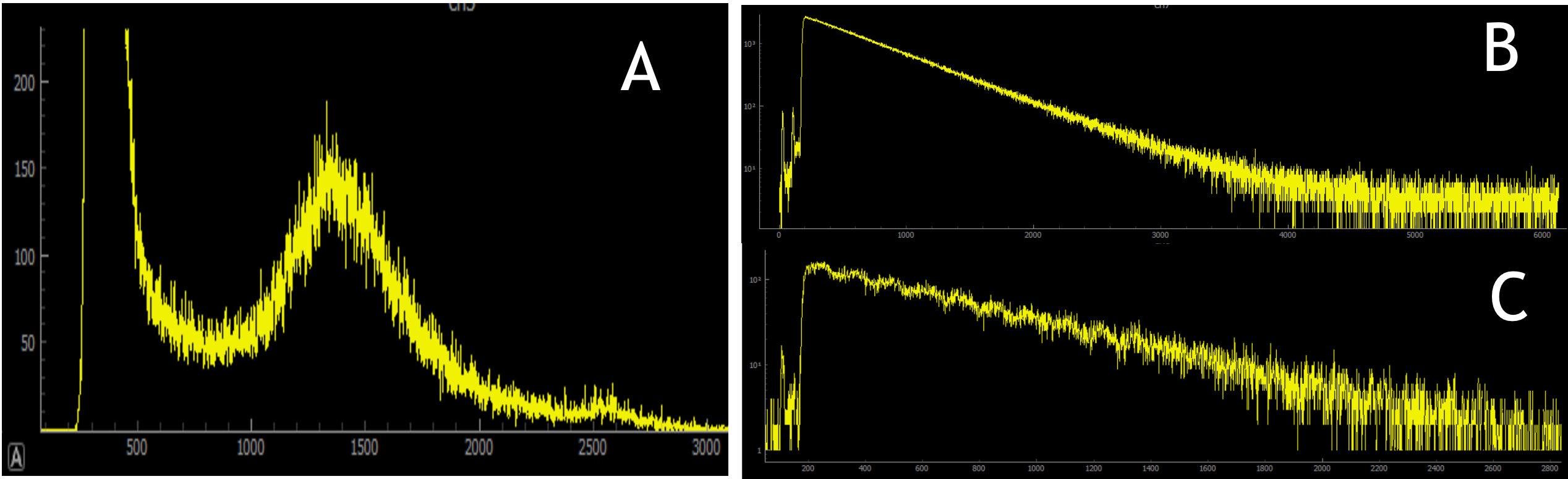
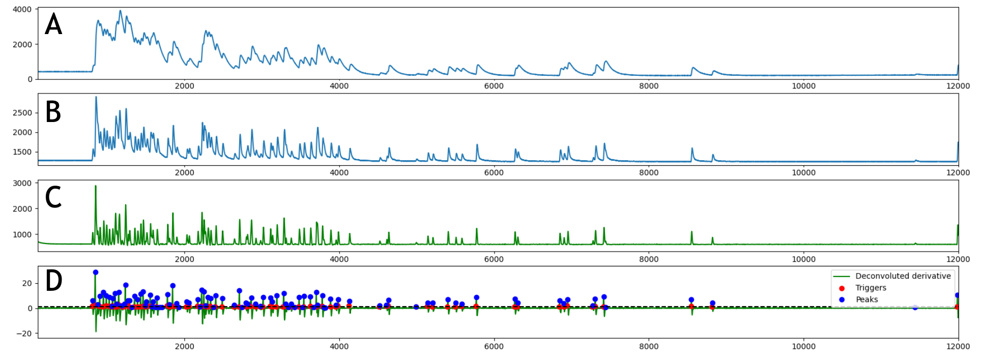
After the transfer, the software on the Zynq CPU initiates the real-time processing pipelines. These pipelines consist of the following elements: deconvolution, denoise, trigger (threshold or derivative), peak detection, amplitude spectrum, and lifetime histogram.

The waves are then packaged using FlatBuffers and sent via KAFKA to the ISIS backend. Similar- ly, events extracted from the online analysis are sent back as lists, packaged with FlatBuffers, and dispatched via Kafka.

Through ZeroMQ, IBEX can access all lifetime and energy histograms, as well as the dark count histograms computed in the FPGA, and display them in real-time to the user.

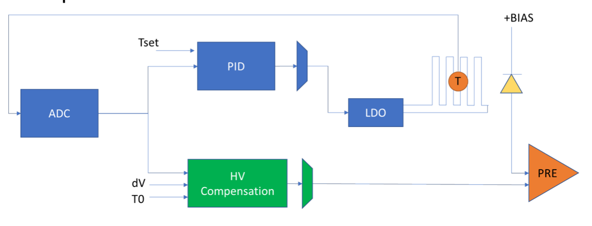
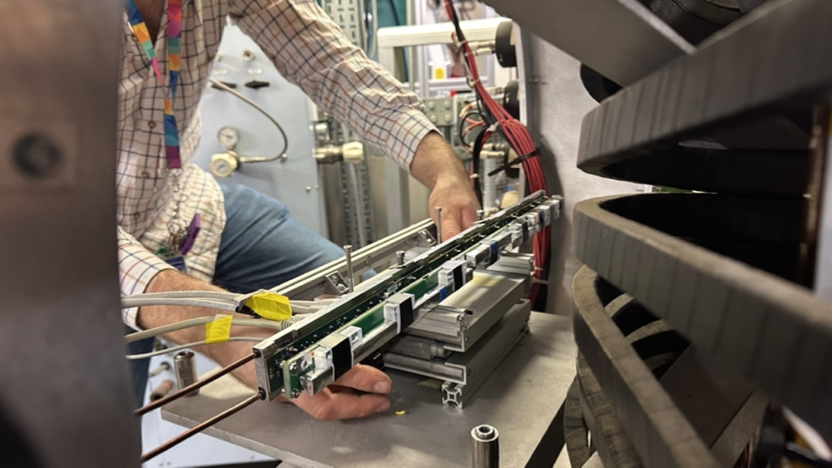
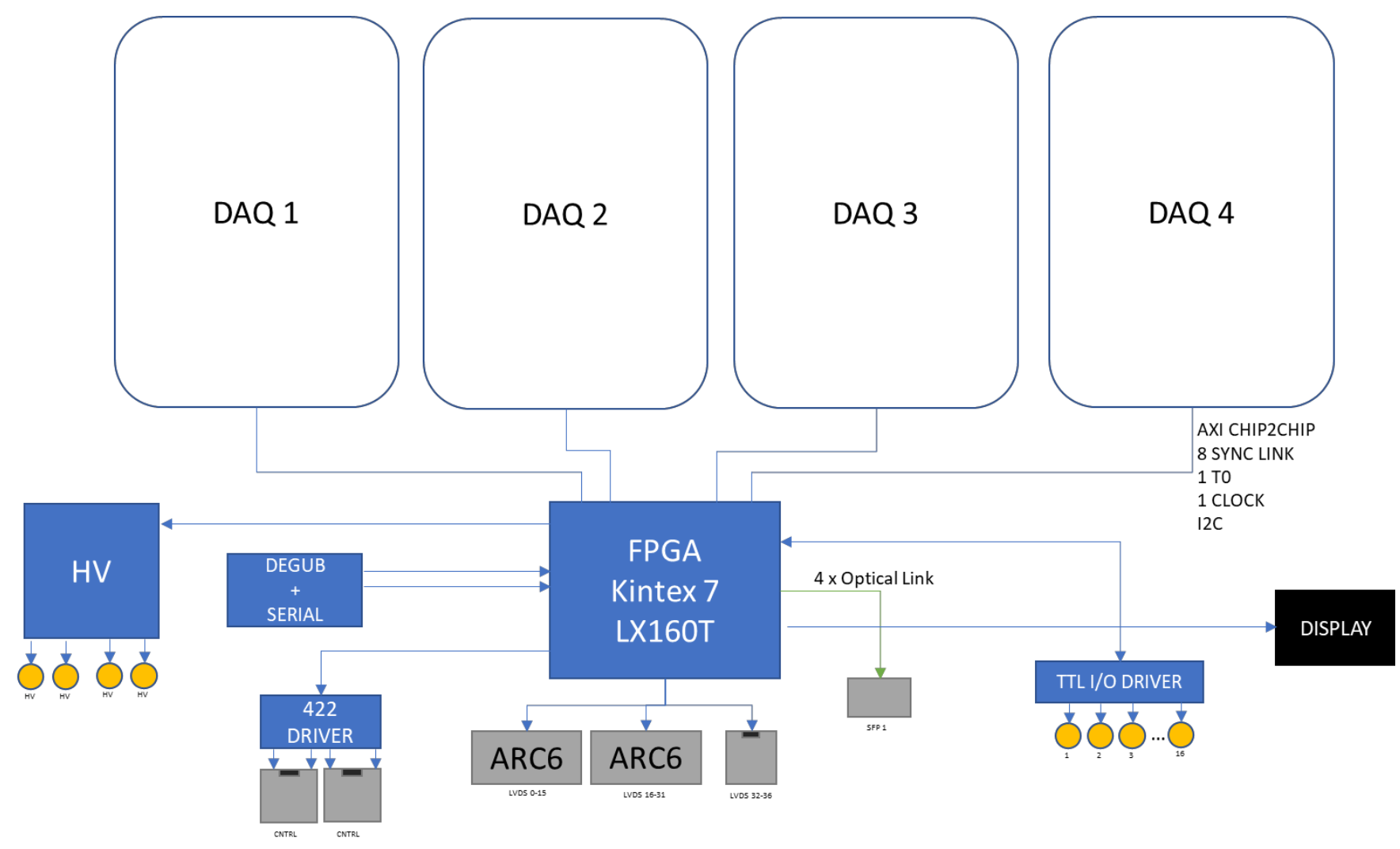
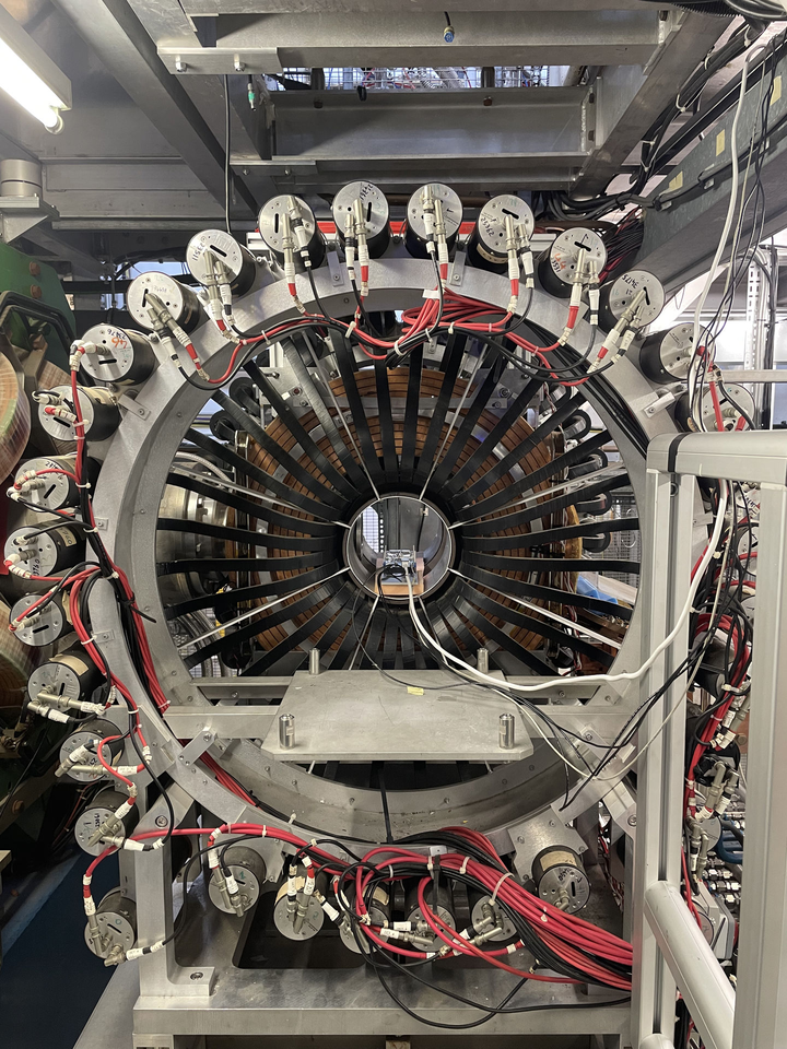
The base of the instrument is tasked with receiving external digital signals such as the trigger, the common clock, and the status packet—a digital packet periodically sent by the ISIS backend containing information such as the timestamp, run number, and veto signals. The base synchro- nizes and distributes this information to all DAQs. Furthermore, it powers the staves, monitors, and controls parameters such as the SiPM bias and temperature, and provides the bias to the SiPMs through four HV generators.


Diagram of the DAQ121 digitizer. 4 DAQ are interconnected with a base board FPGA using AXI Chip2Chip. The base FPGA implements a complex rout- er that can connect any I/O of the frontal panel with digital signal in the DAQ. Base also implements the ISIS status packet decoder logic
Block diagram of the DAQ. The Zynq U+ is connected with 16x12.5 Gbps links to ADS9234 ADC, 12bit 1 Gsps. The FPGA provide common clock and SYNC distribution and interfaces with the base via AXI Chip2Chip. The firmware is partitioned between PL and PS to exploit the best capabilities of the SoC
Block diagram of the digitizer firmware. When trigger condition is verified the digitizer dump up to 120k samples per channels ins a UltraRAM. A interrupt in- duces the software on the PS to start a DMA transfer to collect the waveform and real time process them with complex algorithms.
(a) Energy spectrum measured on MUSR using the prototype of the stave detector. The energy spectrum is im- portant to evaluate the energy cut on the events to be considered on the lifetime spectrum (b) lifetime spectrum of empty beam (c) lifetime spectrum in presence of a sample in MUSR detector. Oscillations are clearly visible.

Deconvolution Algorithm

Pulse deconvolution, crucial in high-rate data acquisition systems like those used in particle physics experiments, is employed to separate overlapping signals in rapid sequences, especially in contexts such as muon spectroscopy. This technique becomes essential when detectors face “pulse pile-up”, where particles hit so swiftly that their signals overlap, forming a complex composite signal. The accuracy in counting and identifying distinct events by the detector is contingent on its ability to resolve these overlapping events. To address this, pulse de-convolution applies mathematical algorithms to the composite signal to differentiate individual pulses. Significantly, this operation is executed directly within the FPGA of the digitizer. Integrating pulse deconvolution into the FPGA allows for real-time processing of the signal, ensuring that the detector rapidly and accurately separates and analyzes individual events from the stream of overlapping data, enhancing the detector’s effective count rate and the overall quality of the data collected.

(a) signal from SiPM from a detector placed in the middle of the beam of MUSR. This is the maximum rate we can expect even from future experiments (b) Signal after analog pole-zero implemented on the stave front end. (c) signal after digital deconvolution (d) second derivative of the deconvolved signal used to identi- fy the events (trigger) and the position of the peak.