Description
The i-Spector is a solution dedicated to those users that need the versatility of a full compact single photodetection system for spectroscopy applications
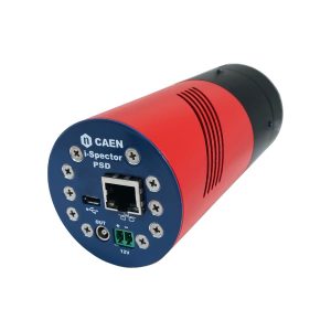
It is a fully-integrated tube designed to replace existing systems based on PMTs. This compact unit is based on a SiPM area (18×18, 24×24 or 30×30 mm2) with preamplifier stage, integrated power supply for SiPM biasing with temperature feedback loop and a monitor for temperature, current and voltage. The i-Spector can be controlled through Ethernet. The output is a fast analog signal that can be digitized or processed with a common Digitizer, MCA or discriminator/TDC chains.
i-Spector PLUS model integrates an additional Timing Unit that is able to correlate the detector signal with external signals. It is designed to perform event timestamping, ToF measurements, coincidence between multiple i-Spector modules and photon counting.
The device can be controlled via ethernet connection and provide an amplified signal on an analog output. If dynamic change of parameters and monitor is not required, the configuration could be stored in the internal flash and the module could be used as a stand-alone unit without any external interconnection except the analog signal output as a standard PMT. This module can be used in combination with 725 and 730 Digitizer families.
i-Spector can be coupled with CsI, LaBr, NaI(Tl), BGO, Lyso, and others scintillator.
- All-in-one detector and preamplification electronics for Gamma Spectroscopy
- Based on a SiPM area up to nearly 1.5 inch2
- 20-80 V Integrated High Voltage for SiPM biasing
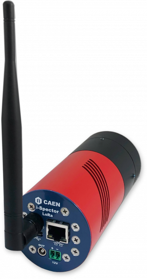
- i-Spector PLUS version with embedded timing unit for coincidence and ToF measurements among multiple devices
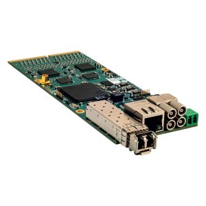
- OEM electronics or detector assembly
- Assembly with CsI scintillator:
- 18x18x30 mm3
- 24x24x30 mm3 (approx. 1x1x1.2 inch3)
- 30x30x38 mm3 (approx. 1.2×1.2x 1.5 inch3)
- Other assembly option available on request: NaI, BGO, LYSO, LaBr3 or any other compatible scintillator
- Demountable mechanics to easily change crystal
- Ethernet connection to PC
- Web-based configuration and monitor interface
- Compact form factor
- Ø 60 mm, h 90 mm (OEM)
- Ø 60 mm, h 135 mm (ASSEMBLY)
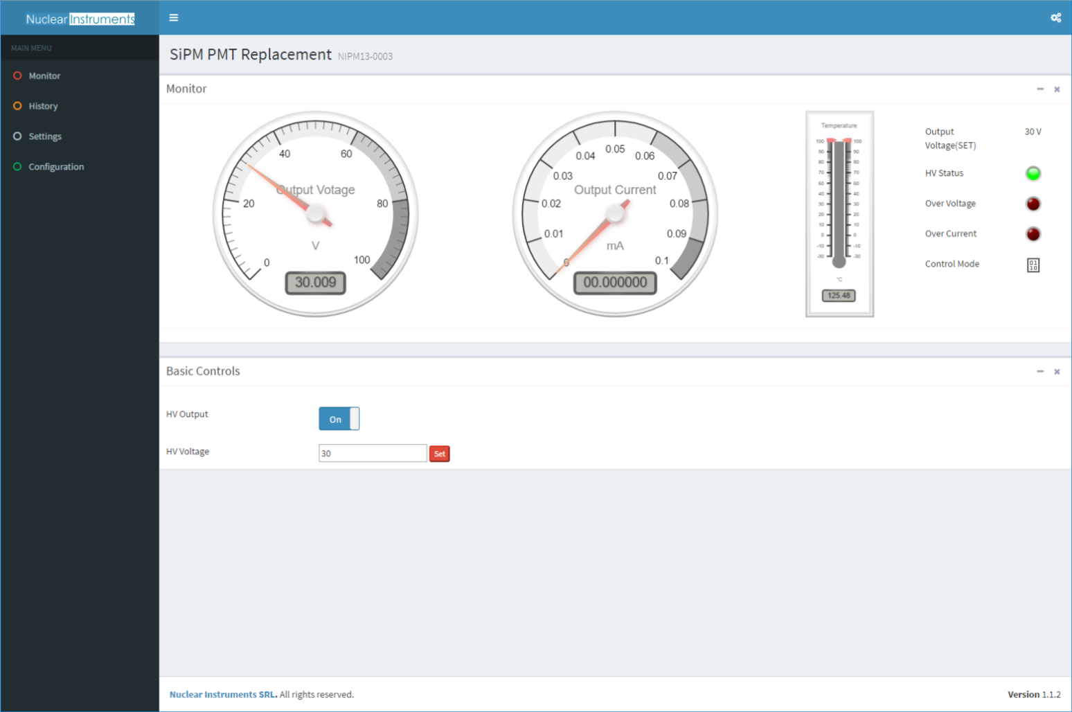
WEB BASED INTERFACE
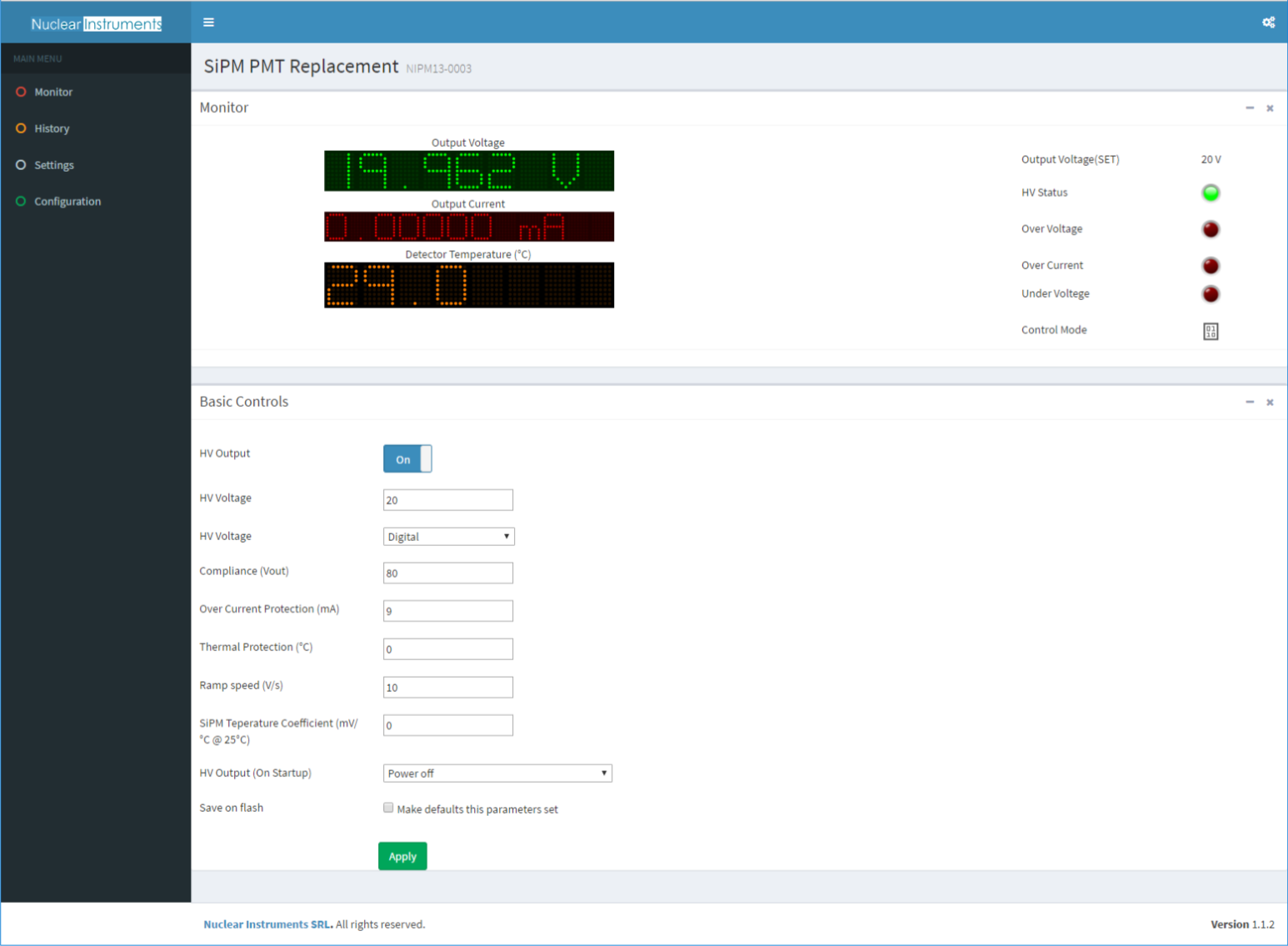
The homepage show the status of the HV generator (voltage, current, enable and protection) and the temperature on the detector. User can power on/off the HV and set the output voltage. On the left menu it is possible to access to the secondaries pages:
- Monitor: home page with HV and detector status
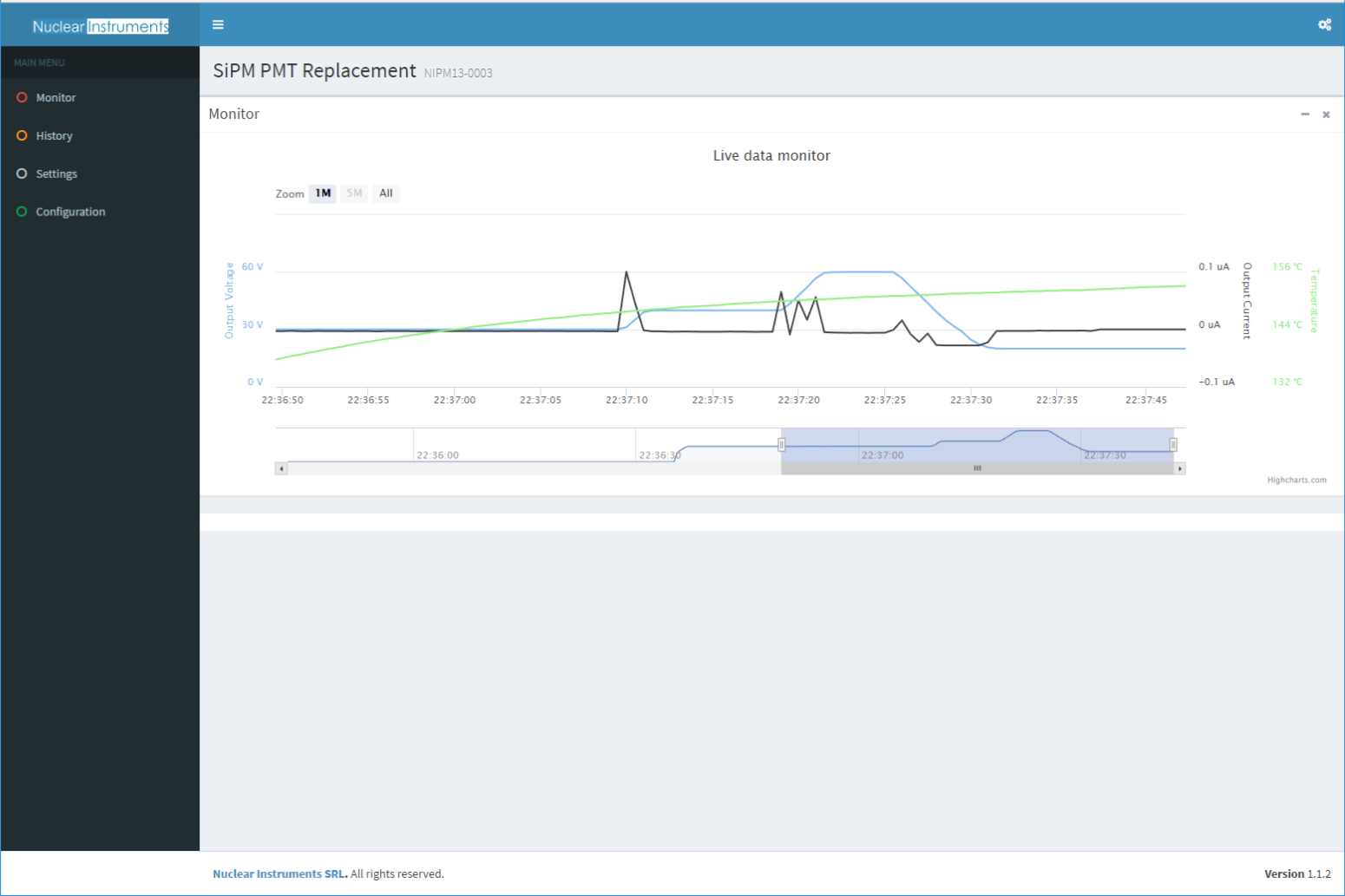
- vHistory: download last hour of data (votage, current, and temperature) from the microcontroller and then accumulate data forever until the page is open
- Settings: advanced settings for the HV controller like temperature compensation, protection and HV status on power on
- Configuration: ethernet configuration
The NIPM13 module has an internal circular buffer memory of an hour where it stores voltage, current and temperature of the sensor. The history page download this information that are always sampled even if the history page is not opened. When the user open this page last hour of data is immediatly downloaded and then every second the whole data set is updated. If the page is opened there isn’t a real limit to the number of points that the plots will show. It depends only by the ram memory of the computer.
In the settings page user can program the following parameters:
- HV ON/OFF: switch on/off the HV power supply using the programmed ramp
- HV Voltage: Set the desidered HV voltage
- HV mode: Select between Digital and Temperature Compensate. When Temperature Compensate is selected, the SiPM HV voltage will be automatically adjoust to correct the temperature drift changing.
- Compliance (Vout): set the maximum Vout. If the ADC measure an higher voltage, the HV setpoint will be adjoust to limit the output voltage
- Over current protection: If the output current overcomes this limit the HV output is immediatly switched of without any ramp. This is not a current limitation but a protection system to limit the current in case of short circuit or if the SiPM matrix is accidentally exposed to ambient light while it is powered on
- Ramp Speed: Ramp up/down applied to the HV voltage to limit the derivate of the HV to do not damage AC coupled ASIC IC
- SiPM temperature Coefficient This coefficient is applied to the HV output voltage reducing or increasing the nominal HV voltage by the following formula Vout = Vset – Tcoef*(T-25)
- For example, if Vset = 50v, Tcoef =50mV/°C and T=35°C Vout will be corrected of 500mV. So the Vout = 49.5v
- HV Output on startup: select the status of the HV when the power is applied to the NIPM13 device. If user wants to operate without ethernet connection to the device, it is possible to set HV output voltage and select Power ON in the HV Output on startup.
This product is sold with CAEN