QMPD-2 – Quantum Multi Photon Detector
QMPD-2 (Quantum Multi Photon Detector) is the SiPM detector head of the QuantumBox photon-number-resolving chain, paired with the optional QMPD-1 bias & control unit (both described below).
Built around a room-temperature Hamamatsu S13360 1.3 × 1.3 mm² SiPM, the QMPD-2 resolves the exact number of photons in each light pulse — true photon-number resolution (PNR) — over a 10–200 p.e. dynamic range, with no cooling required.
A key strength of the QMPD-2 is its mechanical compatibility with the Thorlabs® 30 mm Cage System: it mounts into standard 30 mm cage assemblies and works with common user-replaceable terminated-fiber adapters (FC / SMA / PC / LC / ST), with an adjustable fiber-to-SiPM distance — so it integrates into an existing optical bench with no custom optomechanics.
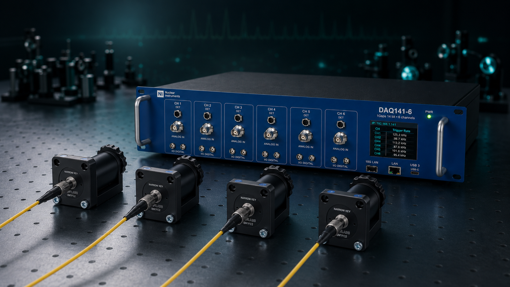
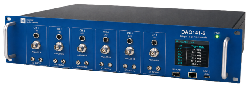
The detector head can be powered and read directly by a DAQ141-6 digitizer — which supplies the SiPM bias, the ±6 V preamplifier rails, temperature feedback and digital gain control over a single M8 cable — or made fully stand-alone with the QMPD-1 unit, for example when used with the 32-channel DAQ141.
Why QMPD-2
- Hamamatsu S13360 SiPM, 1.3 × 1.3 mm² — true photon-number resolution
- Resolves the exact photon number in every pulse, over a 10–200 p.e. range
- Room-temperature operation — no cooling, no cryogenics
- Variable-gain front-end (TIA + ×6) matched to the optical dynamic range
- Single-photon resolution with < 0.3 p.e. pk-pk baseline noise
- Compatible with the Thorlabs® 30 mm cage system, user-replaceable FC / SMA / PC / LC / ST fiber adapters
- Powered and read directly by a DAQ141-6, or stand-alone with the QMPD-1
- Part of the QuantumBox photon-counting and time-tagging chain
QMPD-2 — Detector Head
The QMPD-2 is the optical front-end of the QuantumBox chain. Inside the head, light delivered through the fiber adapter illuminates the Hamamatsu S13360 SiPM; the resulting current pulse is converted to a voltage by the variable-gain transimpedance amplifier (TIA), amplified by a fixed ×6 output stage, and presented on the MCX output as a fast analog pulse whose area is proportional to the number of detected photons.
All bias and control signals reach the head through a single M8 cable: the programmable SiPM bias, the ±6 V ultra-low-noise preamplifier rails, the digital gain selection, an analog temperature-feedback line and a one-wire bus carrying the calibration EEPROM and board-temperature data. The same cable is driven either by a DAQ141-6 — which integrates the full front-end supply for up to six heads — or by a QMPD-1 unit when the head is used stand-alone or with the 32-channel DAQ141.
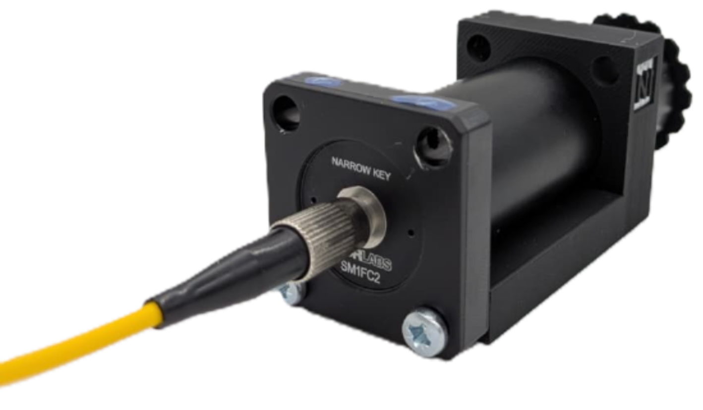
The QMPD-2 detector head: a fiber-coupled S13360 SiPM in a 30 mm cage-compatible cylinder housing, with MCX signal output and a single M8 power/control connector.
The QMPD-2 detector head: a fiber-coupled S13360 SiPM in a 30 mm cage-compatible cylinder housing, with MCX signal output and a single M8 power/control connector.
Key Features
- Hamamatsu S13360 SiPM, 1.3 × 1.3 mm² active area
- Selectable 25 µm or 50 µm cell pitch
- True PNR via multi-cell Geiger-mode matrix
- Room-temperature operation — no cooling needed
- On-board temperature monitor
- Variable-gain TIA + fixed ×6 output stage
- Selectable ranges: 20 / 50 / 150 / 200 photons (10–200 p.e.)
- Baseline noise < 0.3 p.e. pk-pk, temperature-compensated gain
- MCX signal output · M8 power/control
Variable-Gain Front-End
A variable-gain transimpedance amplifier with selectable feedback (20 / 50 / 150 / 200 photon ranges) feeds a fixed ×6 output stage. Selecting the TIA gain matches the optical dynamic range to the measurement — from single photons up to large multi-photon pulses — keeping the photon-number peaks well separated.
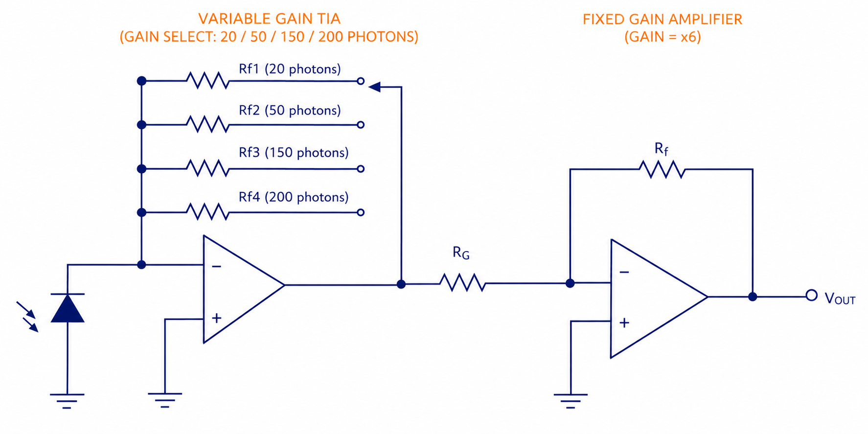
Figure 1 — QMPD-2 front-end: a variable-gain transimpedance amplifier with selectable feedback (20 / 50 / 150 / 200 photon ranges) feeding a fixed ×6 output stage.
Figure 1 — QMPD-2 front-end: a variable-gain transimpedance amplifier with selectable feedback (20 / 50 / 150 / 200 photon ranges) feeding a fixed ×6 output stage.
Optomechanics & Fiber Coupling
The QMPD-2 is mechanically compatible with the Thorlabs® 30 mm cage system: its cage-cylinder housing mounts into standard 30 mm cage assemblies with an adjustable fiber-to-SiPM distance. Light is delivered through user-replaceable terminated-fiber adapters in all common terminations — FC, SMA, PC, LC, ST — so the same head can be matched to virtually any fiber in the lab.
Trademark notice. This product is manufactured by Nuclear Instruments and is mechanically compatible with selected Thorlabs optomechanical components. Thorlabs is a trademark of Thorlabs, Inc. This product is not manufactured, endorsed, or approved by Thorlabs.
Connectors & Interfaces
| Connector / Interface | Description |
|---|---|
| MCX (signal out) | Coaxial analog output of the detector head — connects to a DAQ141-6 / DAQ141 ADC input |
| M8 (power & control) | 8-pin industrial connector carrying the SiPM bias, ±6 V preamplifier rails, digital gain control, analog temperature feedback and the one-wire calibration/temperature bus |
| Fiber input | Compatible with user-replaceable Thorlabs® terminated-fiber adapters (FC / SMA / PC / LC / ST); adjustable fiber-to-SiPM distance |
| Cage interface | 30 mm four-rod cage — compatible with the Thorlabs® cage system |
| QMPD-1 Bias output | Programmable SiPM HV bias 20 ÷ 85 V (10 mA) delivered to the head over the M8 cable |
| QMPD-1 USB | USB control interface for the ZEUS software and the C / Python libraries |
| QMPD-1 UART / I²C | Digital control and monitoring bus; an open-source C library supports multiple devices on a single bus |
| QMPD-1 Analog | Analog control input and high-resolution voltage / current monitoring |
Characterization & Performance
The plots below were acquired with a QMPD-2 head illuminated by a 6 ns pulsed laser through a fiber, with the front-end gain set for a 50 p.e. full-scale range. They show the single-pulse response, the photon-number resolution and the baseline noise that define the detector’s single-photon performance.
Single-Pulse Response
A single laser pulse produces a fast SiPM signal whose area is proportional to the number of detected photons. The leading edge rises in about 10 ns, the pulse reaches a full width at half maximum of roughly 35 ns, and an exponential tail returns to baseline in approximately 100 ns.
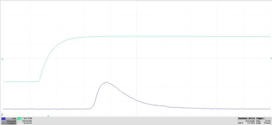
Figure 2 — Laser-triggered single pulse. Top trace: 6 ns laser trigger reference; bottom trace: detector output (~10 ns rise, ~35 ns FWHM). Front-end gain set for 50 p.e. full-scale.
Figure 2 — Laser-triggered single pulse. Top trace: 6 ns laser trigger reference; bottom trace: detector output (~10 ns rise, ~35 ns FWHM). Front-end gain set for 50 p.e. full-scale.
Photon-Number Resolution
Acquired in persistence mode over many laser shots, the pulse amplitude does not form a continuous blur but clusters into discrete, well-separated bands. Each band corresponds to an exact number of detected photons — direct evidence of true photon-number resolution. The QMPD-2 keeps these peaks distinct across its full 10–200 p.e. range.
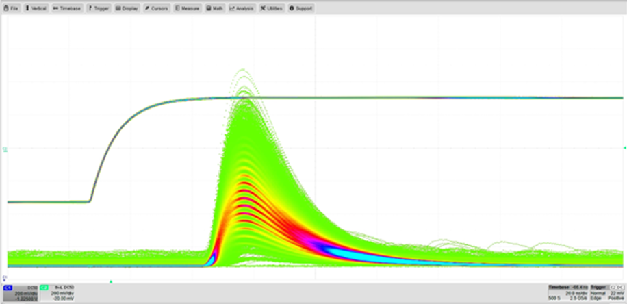
Figure 3 — Multiphoton persistence (50 p.e. full-scale gain): each discrete amplitude band is one additional detected photon.
Figure 3 — Multiphoton persistence (50 p.e. full-scale gain): each discrete amplitude band is one additional detected photon.
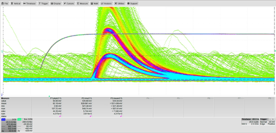
Figure 4 — Persistence of the first two photon levels; the cursors measure the single-photon-equivalent (SPE) step — the amplitude added by each individual photon at this gain (≈ 42.8 mV).
Figure 4 — Persistence of the first two photon levels; the cursors measure the single-photon-equivalent (SPE) step — the amplitude added by each individual photon at this gain (≈ 42.8 mV).
Baseline Noise
With the detector in the dark, the baseline noise measures 13 mV peak-to-peak (1.5 mV rms). Relative to the 42.8 mV single-photon step this is below 0.3 p.e. peak-to-peak, so adjacent photon-number peaks stay cleanly separated and the single-photon level is unambiguously resolved.
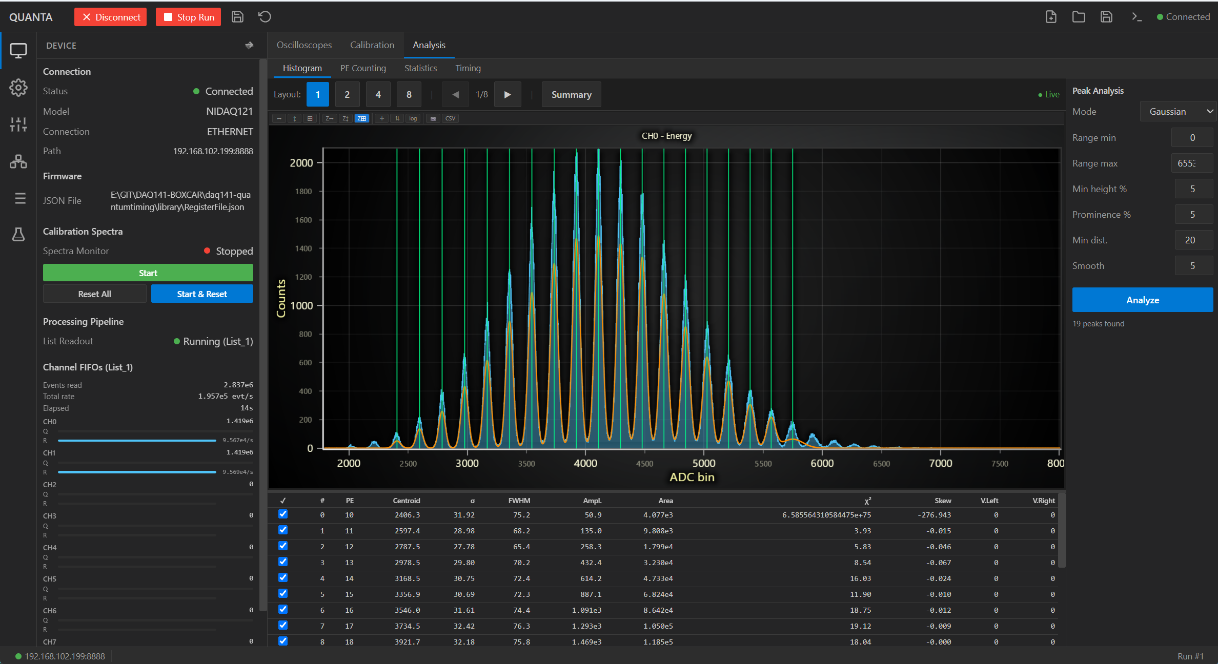
Multi-Photon Spectrum Analysis — Poisson-Constrained Fit
The pulse-height (charge) spectrum is fitted with a single, joint model: a sum of Gaussian peaks whose areas are constrained by a Poisson distribution. The macroscopic shape of the spectrum (the “belly”) emerges naturally as the Poisson envelope of the peaks — it is not modelled with an ad-hoc polynomial baseline. This collapses the free parameters from 3 + 3N (66, for 21 independent peaks plus a polynomial) to just 8.
On a representative dataset the fit converged on 21 resolved peaks (n = 0…20) with a mean photon number ⟨n⟩ = 8.244 ± 0.008:
- Gain (linearity): 202.823 bin/photon; an independent linear fit on the first six photon centroids agrees to within 0.77 % across the full dynamic range
- Width law σₙ² = σₑ² + n·σ_g² describes the broadening of all 20 non-pedestal peaks (electronic noise σₑ = 3.29 bin, per-photon gain spread σ_g = 9.54 bin)
- Fano factor F = 0.997, confirming the Poisson nature of the source
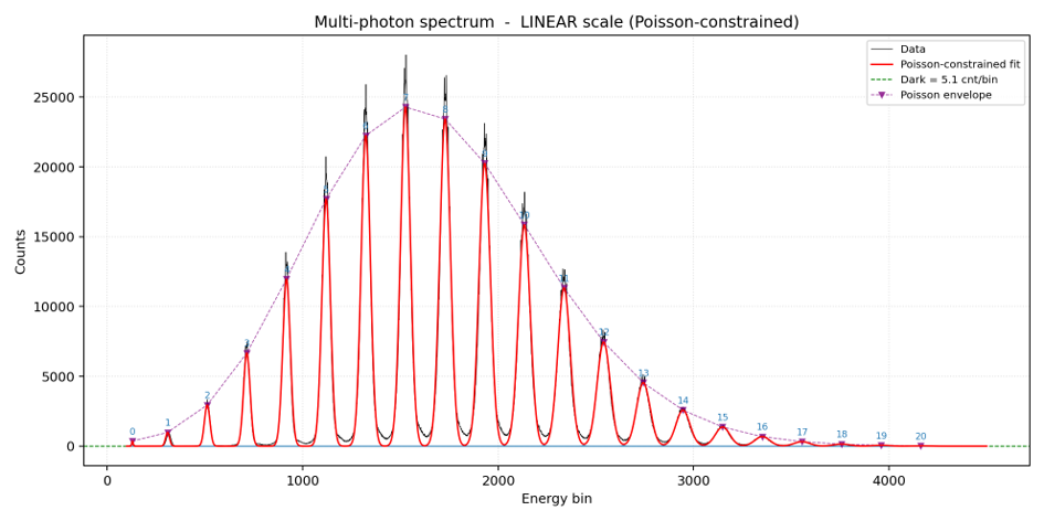
Measured spectrum (black), Poisson-constrained joint fit (red), individual Gaussians (blue) and the Poisson envelope connecting the peak amplitudes (purple). Linear scale.
Measured spectrum (black), Poisson-constrained joint fit (red), individual Gaussians (blue) and the Poisson envelope connecting the peak amplitudes (purple). Linear scale.
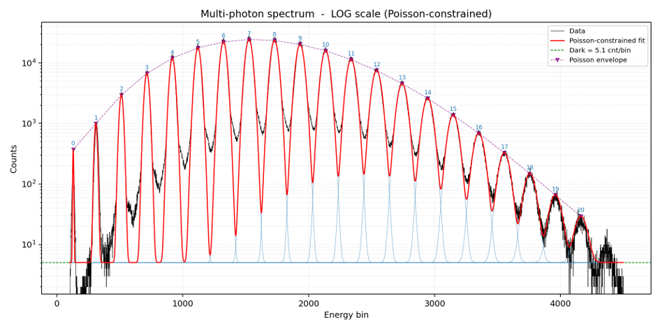
The same fit on a logarithmic scale: the Poisson envelope is visible as the smooth modulation of the peak heights, peaking at n ≈ 8.2.
The same fit on a logarithmic scale: the Poisson envelope is visible as the smooth modulation of the peak heights, peaking at n ≈ 8.2.
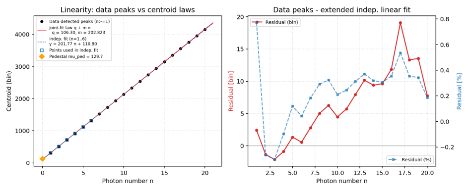
Centroid vs. photon number: the gain is linear at 202.823 bin/photon, with residuals staying below 0.77 % across the full range.
Centroid vs. photon number: the gain is linear at 202.823 bin/photon, with residuals staying below 0.77 % across the full range.
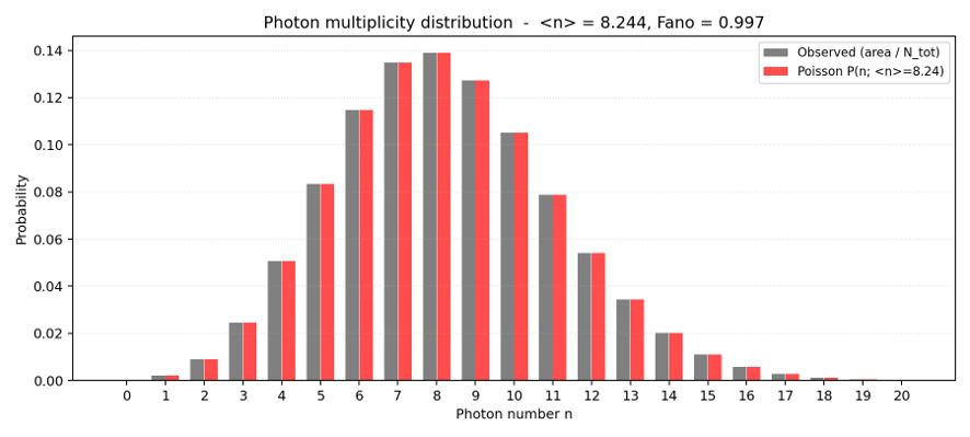
Observed multiplicity (peak area / N_tot, grey) vs. the Poisson distribution at the fitted ⟨n⟩ = 8.244 (red), Fano factor 0.997.
Observed multiplicity (peak area / N_tot, grey) vs. the Poisson distribution at the fitted ⟨n⟩ = 8.244 (red), Fano factor 0.997.
QMPD-1 — Bias & Control Unit
The QMPD-1 is the power supply and controller for the QMPD-2 detector head, designed to run the detector fully stand-alone, with no DAQ141-6 in the system. While a DAQ141-6 can power and control the head directly, the QMPD-1 supplies everything the detector needs from a single compact box — making it the natural companion when the QMPD-2 is used with the 32-channel DAQ141 or in any setup without an integrated front-end supply.
Over the single M8 cable it delivers the programmable SiPM high-voltage bias, the ±6 V ultra-low-noise preamplifier rails and the digital front-end gain control, while continuously monitoring output voltage and current:
- The high-voltage section provides a programmable SiPM bias from 20 to 85 V at up to 10 mA, with very low ripple (< 0.1 mVpp typical) and high-resolution voltage and current read-back. Programmable temperature compensation corrects the bias against the SiPM temperature coefficient, keeping the gain — and therefore the spacing of the photon-number peaks — stable over temperature.
- Front-end gain is set digitally: the QMPD-1 selects the variable-gain TIA feedback of the QMPD-2 (the 20 / 50 / 150 / 200-photon ranges), matching the optical dynamic range to the measurement with no manual intervention on the detector head.
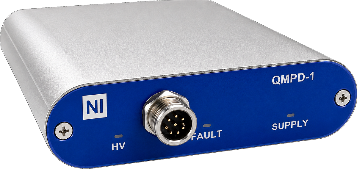
The QMPD-1 bias & control unit: stand-alone power supply and controller for the QMPD-2 — HV bias, ±6 V preamplifier rails, digital gain control and monitoring over a single M8 cable.
The QMPD-1 bias & control unit: stand-alone power supply and controller for the QMPD-2 — HV bias, ±6 V preamplifier rails, digital gain control and monitoring over a single M8 cable.
QMPD-1 Features
- 20 ÷ 85 V (10 mA) programmable bias output, suitable for large SiPM matrices
- Very low ripple (< 0.1 mVpp typical)
- ±6 V ultra-low-noise preamplifier supply
- Digital front-end gain control of the QMPD-2
- Analog and digital control (UART, I²C, analog & USB)
- High-resolution voltage and current monitoring
- Programmable temperature compensation
- Multi-unit addressing over the I²C bus
- ZEUS 2 control software · open-source C & Python libraries (GitHub)
ZEUS 2 Control Software
Both the HV bias and the front-end gain are managed from ZEUS 2, the control application for the QMPD-1. Connected over USB (or Ethernet / I²C), ZEUS 2 lets the user set and read back the SiPM bias voltage and the detector gain range, monitor live voltage, current and temperature, enable temperature compensation and store per-device calibration. The same functions are exposed programmatically through open-source C and Python libraries, and the I²C bus allows several QMPD-1 units to be addressed together — so a multi-detector array can be configured and monitored from one ZEUS 2 session or script.
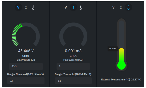
ZEUS 2 live monitoring: per-channel SiPM bias voltage, current and temperature, each with an editable set-point and a configurable danger threshold.
ZEUS 2 live monitoring: per-channel SiPM bias voltage, current and temperature, each with an editable set-point and a configurable danger threshold.
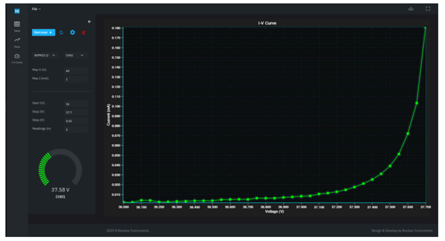
ZEUS 2 I–V curve tool: an automated bias sweep that traces the SiPM current-vs-voltage characteristic for breakdown-voltage extraction and diagnostics.
ZEUS 2 I–V curve tool: an automated bias sweep that traces the SiPM current-vs-voltage characteristic for breakdown-voltage extraction and diagnostics.
Full Specifications
QMPD-2 — Detector Head
| Parameter | Value |
|---|---|
| Sensor | Hamamatsu S13360 SiPM |
| Active area | 1.3 × 1.3 mm² |
| Cell pitch | 25 µm / 50 µm (option) |
| Photon-number resolution | True (multi-cell Geiger-mode) |
| Operating temperature | Room temperature, no cooling |
| Temperature monitor | Analog feedback + 1-wire EEPROM |
| Preamplifier | Variable-gain TIA + fixed ×6 |
| Gain ranges | Selectable feedback — 20 / 50 / 150 / 200 photons |
| Dynamic range | 10–200 p.e. |
| Single-photon step | ≈ 42.8 mV (at 50 p.e. full-scale) |
| Baseline noise | 13 mV pk-pk (1.5 mV rms) · < 0.3 p.e. pk-pk |
| Pulse rise time (10–90 %) | ~10 ns |
| Pulse width (FWHM) | ~35 ns |
| Pulse decay to baseline | ~100 ns |
| Mounting | 30 mm cage-cylinder, Thorlabs®-compatible |
| Fiber coupling | FC / SMA / PC / LC / ST (replaceable) |
| Fiber-to-SiPM distance | Adjustable |
| Signal output | MCX |
| Power & control | M8, 8-pin |
| Power source | DAQ141-6 or QMPD-1 |
QMPD-1 — Bias & Control Unit
| Parameter | Value |
|---|---|
| Bias output range | 20 ÷ 85 V |
| Maximum bias current | 10 mA |
| Bias voltage ripple | < 0.1 mVpp typical |
| Preamplifier supply | ±6 V, ultra-low noise |
| Front-end gain control | Digital |
| Control interfaces | UART, I²C, analog, USB |
| Voltage & current monitoring | High-resolution |
| Temperature compensation | Programmable |
| Control software / libraries | ZEUS 2, C & Python (GitHub) |
| Detector capacity | 1× QMPD-2 / large SiPM matrix |
Part of the QuantumBox System
The QMPD-2 and QMPD-1 are components of the QuantumBox photon-number-resolving detection chain: